
2500 named model · Supplier parameter image review
2500 earth drill for the listed 1–3 t carrier class
A small-carrier earth-drill entry with an official parameter image. Compare its reported hydraulic ranges, drive dimensions and ground-dependent depth references before specifying the mounting and auger package.
Read the drive ranges with their source labels
1–3 t describes the excavator, while 50 kg is the reported product weight.
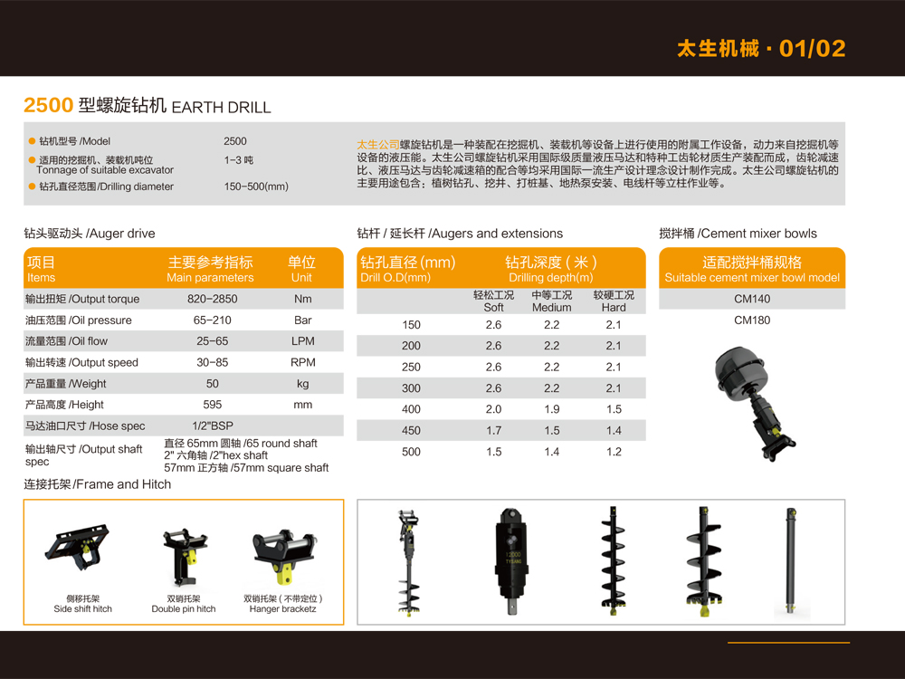
The 2500 page identifies a planetary drive and a retained single-piece output shaft. [1] Its embedded Chinese/English parameter image contains the following values, visually checked rather than inferred from the model number. [2]
| Source label | Reported value | Meaning to confirm for the delivered kit |
|---|---|---|
| Output torque | 820–2850 N·m | Torque against pressure and actual operating point |
| Oil pressure | 65–210 bar | Permitted supply conditions, duty and return limits |
| Oil flow | 25–65 L/min | Carrier auxiliary supply and actual configuration |
| Output speed | 30–85 rpm | Speed/flow relationship and allowed duty |
| Product weight | 50 kg | Which included parts the mass covers |
| Height | 595 mm | Full mounting/auger installation envelope |
| Hose specification | 1/2″ BSP | Thread form, sealing and exact offered connections |
These are supplier catalogue values, not an CivilEquip field test. The image does not provide complete curves or define every range endpoint as one simultaneous operating point. Request current configuration-specific limits rather than assuming maximum torque and maximum speed occur together.
Seven diameter rows, three supplier ground headings
Use the table to discuss tooling and trial conditions.
The image gives a 150–500 mm drilling-diameter range and the following depth references for augers/extensions. It labels ground only “soft”, “medium” and “hard”; strength, soil classification, obstacle conditions and test procedure are not established.
All seven source rows shown.
| Diameter (mm) | Soft (m) | Medium (m) | Hard (m) |
|---|---|---|---|
| 150 | 2.6 | 2.2 | 2.1 |
| 200 | 2.6 | 2.2 | 2.1 |
| 250 | 2.6 | 2.2 | 2.1 |
| 300 | 2.6 | 2.2 | 2.1 |
| 400 | 2.0 | 1.9 | 1.5 |
| 450 | 1.7 | 1.5 | 1.4 |
| 500 | 1.4 | 1.4 | 1.2 |
For example: 400 mm × 2 m
The source’s 400 mm row shows 2.0 m only under “soft”; its “medium” and “hard” columns show 1.9 and 1.5 m. Describe the actual ground and ask the supplier to propose the auger, pilot/teeth and extensions. This reference cannot promise a two-metre result in every ground type.
Depth figures do not establish holes per hour, spoil-clearance performance or acceptable obstacles. Agree an application-specific tooling proposal and trial if the site conditions require it.
Choose one shaft connection and one carrier mount
Published output-shaft options
- 65 mm round shaft
- 2-inch hex shaft
- 57 mm square shaft
Return the actual coupling, retention and auger/extension drawing. Similar dimensions or photographs do not establish a fit.
Mount illustrations
- Side-shift hitch
- Double-pin hitch
- Hanger bracket
Confirm the quoted option, carrier pins/coupler, clearances and allowed attachment/tooling load with the actual installation documents.
The manufacturer’s retained-shaft description does not remove the need for supplied-unit instructions and competent installation. Its “never fall out” and competitor-bearing comparison are not independently authenticated safety or life claims.
List the kit and its operating documents
- Drive / hydraulic connection
- Model/configuration, selected shaft, mounting, pins/coupler, hoses and exact fittings
- Ground tools
- Auger size/length, pilot, teeth, extensions and identifiable wear parts
- Separate mixer options
- Source names CM140 and CM180 bowls; confirm bowl, connection and use separately
- Current documents
- Controlled parameters, installation, operating and maintenance/parts information
The download index currently lists zero records. [3] Request documents directly; do not treat the parameter image as a complete operating manual. HSE’s HSG47 overview describes planning, locating services and safe excavation. [4] Assign the actual site/underground-services responsibility independently of selecting the tool, using applicable local requirements.
Does the 2500 model number mean 2500 N·m?
The parameter image reports an 820–2850 N·m range. The model name alone is not an operating rating.
Does a three-tonne carrier guarantee suitability?
The carrier band is a shortlist. Its hydraulic supply, mount, attachment/tooling load and the actual job still require confirmation.
Prepare a 2500 drill-and-tooling request
Sources & review
- Tysang 2500 detail ↗
Model/carrier band, planetary gearbox and supplier-retained-shaft description. No independent life/safety comparison.
2026-10-11 - Official 2500 parameter image ↗
Visually read individual values and seven depth rows. Terms soft/medium/hard are not defined geotechnical classes; no productivity or simultaneous-range-endpoint proof.
2026-10-11 - Tysang download index ↗
Zero current records; request current selected-unit instructions directly.
2026-10-11 - HSE HSG47 overview ↗
Underground-services planning/location/safe-excavation context, not a product approval or complete site method.
2026-10-11
Specifications come from the manufacturer’s published information and the sources above; buying advice is written by CivilEquip with AI assistance. Ask the manufacturer to confirm the data for your configuration. Editorial policy · Report a correction.